Plan the garden, the ground and the water together
Start with where water goes. Review decks, ground levels, building interfaces and maintenance access together, then use the relevant detail sections.
Base guide 21 October 2026 · Visual references updated 25 October 2026 · U.S. homeowner and property-reader focus · Photo-led reading update: 27 October 2026 · Junction and care-plan review: 28 October 2026
123
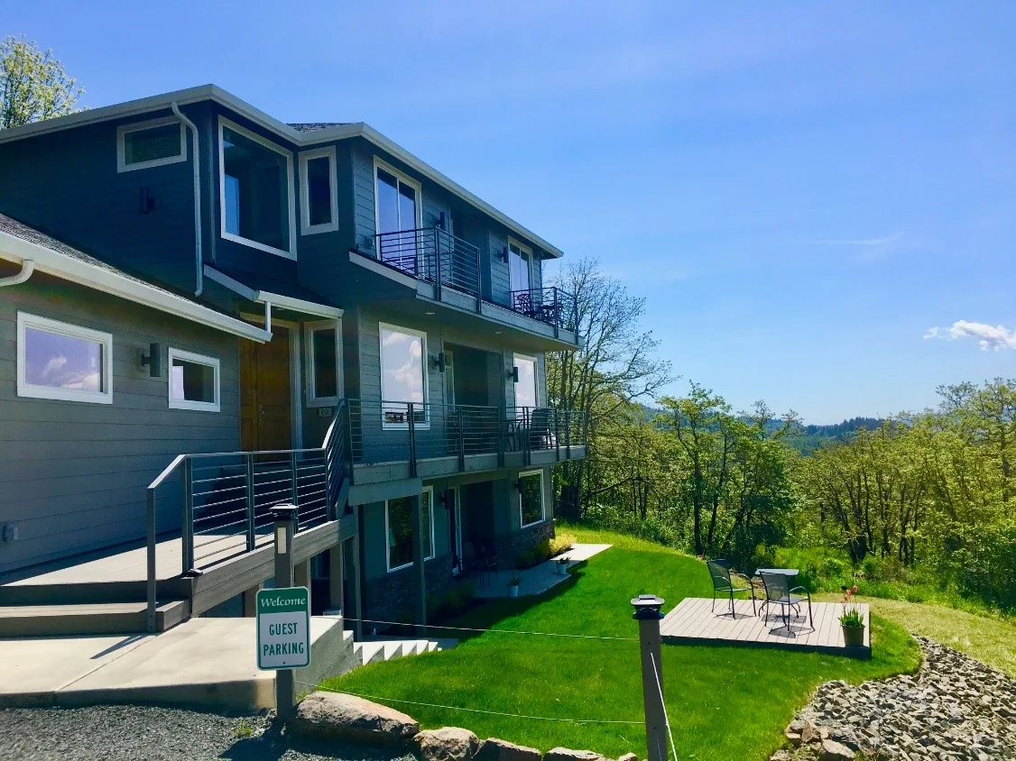
Read the deck and the surrounding ground together. This real residential setting shows three places to start.
Deck at the wall: Look for signs of repeated wetting near the siding and doors. Ask how the wall connection handles water.
Deck edge: Trace where water from the deck surface falls or runs off.
Ground below: Check where the ground receives that water and where it goes next.
Its source concerns wildfire-resistant construction; the photograph does not verify hidden drainage, structural connections or a suitable detail for another site. PNNL / Courtesy of the U.S. Department of Energy · Source record · BASC reuse guidance. Original image unchanged. Reference only; not a DLG project or an endorsement.
Home showing / exterior checklist
Where does the rain go after it hits the deck?
Start at the wall and follow water to its receiving point. Use the numbered photograph to locate the interfaces, then verify the actual property after rain when possible.
Wall & door
Deck surface & edge
Ground or drain
Receiving point
01 / Start at the wall
Look for staining, peeling finishes or soft-looking trim near doors and siding. Ask whether the deck attaches to the house or is self-supporting. If it uses a ledger (the board connecting the deck to the house), ask for photos or drawings showing how its flashing ties into the wall drainage layer.
02 / Follow the surface
Ask whether the surface sheds water at an edge, lets it pass between boards, or drains into a system underneath. A deck over enclosed space needs its own water-control detail. Ask what was installed before assuming how it drains.
03 / Find the outlet
Look for persistent pooling or erosion at the ground below. If a pipe or channel collects water, ask where it discharges and how that outlet can be accessed and maintained.
04 / Request evidence
Ask for dated construction photos, available plans and any applicable permit or inspection records. A photo can locate a junction; concealed flashing, the structural connection and a buried outlet may still be unverified. Flag those for an inspector or qualified contractor.
01 / Understand the site and waterChapters 1–2 · Existing conditions, perimeter drainage and receiving routes.
1. Begin with use and existing conditions
Describe what the outdoor space must do: provide a safe route to the door, accommodate a table, shade a sitting area, support gardening or remain manageable during an owner’s absence. Decide who will maintain it and what equipment they can reasonably use.
Then collect a base plan. Mark property boundaries and known easements, buildings, entrances, trees, utilities, wells, septic facilities and existing drainage features. Identify uncertain records rather than drawing them as confirmed. Photographs during rain can supplement a measured survey, but cannot establish levels or an underground pipe route.
EPA landscape guidance supports reviewing climate, sun, soil and water needs together. Grouping plants by similar irrigation requirements creates hydrozones; new planting also needs an establishment plan. [LW01]
On a narrow screen, scroll the comparison table horizontally.
Area
Brief question
Evidence to collect
Entrance and circulation
Who uses the route, carrying what, in which season?
Measured levels, clear route, surface and access requirements
Terrace and sitting
Where are sun, shade, glare and privacy most useful?
Seasonal observations, furniture layout and maintenance access
Planting
What can thrive in each site’s conditions?
Soil results, exposure, mature spread and local plant advice
Water and services
Where does water enter, collect and leave?
Roof connections, levels, soil assessment and confirmed receiving route
Keep tree protection, future equipment access and the house’s service areas visible when comparing layouts. A garden that blocks a maintenance cover or requires a tank to be moved for repairs has an unresolved brief.
2. Follow the water before changing the ground
Separate roof runoff, surface runoff and the building’s foundation-water arrangements in the survey and brief. Do not assume existing pipes are interchangeable or share a suitable outlet.
ACTUAL PHOTOGRAPH / REFERENCE
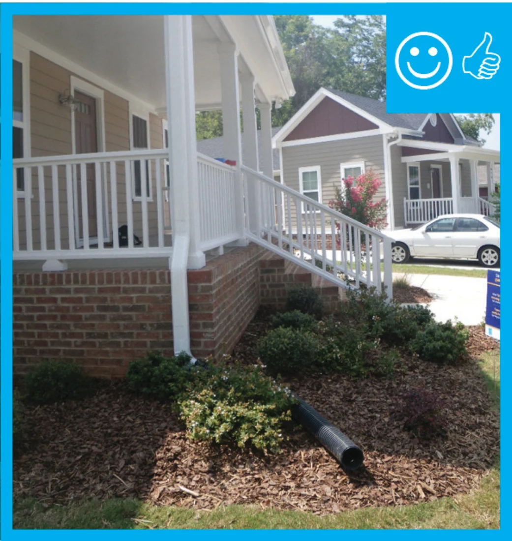
Downspout discharge: follow the receiving route
An EPA/ENERGY STAR reference photograph shows a downspout extension reaching away from a house. The source artwork includes its own historic “right” label; this is not a current local approval, a flow test or a universal distance rule.
Ask: Where does roof water reach the ground or approved receiving point, and how are the route, access and erosion questions recorded?
Photo source & use
EPA / ENERGY STAR / Courtesy of the U.S. Department of Energy. Source record · BASC reuse guidance. Resized and WebP encoded, orientation from metadata, no retouching. Checked 27 October 2026. Not a DLG project or a site-specific installation approval.
DOE building-science guidance explains the role of grading away from a house in moving water away from its foundation. [LW03] The necessary levels and construction details depend on the building, soil, access and local requirements; this guide supplies no universal slope, pipe size or setback.
Ask the designer to show ordinary flow and the route taken when a drain is blocked, a tank is full or a storm exceeds the selected design conditions. Identify the receiving point, its capacity and any permission required. A line disappearing at the edge of a drawing leaves the most important question unanswered.
Record where water collects, how long it remains and whether it reaches doors or below-grade openings. Persistent building dampness needs investigation of the relevant building and site systems. A decorative gravel strip is not evidence of waterproofing or an adequate drainage outlet.
Design review question: What changes downstream, including at neighbouring property, when this terrace, wall or planting bed is built?
Building-perimeter water management
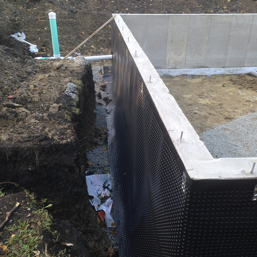
Inspect the wall-to-ground system before backfill. The source identifies a drainage mat and perimeter pipe. Read the visible layers alongside the planned filter, outlet and access records; this view does not establish their continuity or prove acceptance of the completed system. BrightLeaf Homes / Courtesy of the U.S. Department of Energy · Source record · BASC reuse guidance. Original image unchanged. Reference only; not a DLG project or an endorsement.
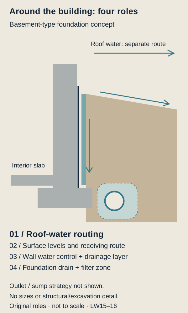
Read the perimeter as several coordinated systems: roof-water discharge, finished surface levels, the below-grade wall’s water-control layers, and any foundation drain with its receiving route. A shallow channel beside paving and a footing drain serve different locations and functions.
Closer look: follow the roof water beyond the visible connection
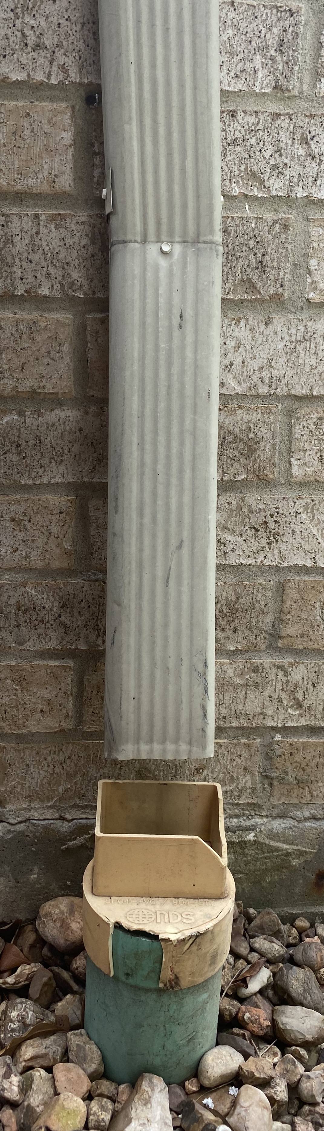
Follow the roof water beyond the visible connection
U.S. reference photograph of a downspout and receptor. The receiving pipe continues out of view. Neither its destination nor a connection to a foundation drain is established by the photograph.
What to ask: Where does this roof-water route discharge, and how will that route and its inspection or maintenance access be documented?Photo: Bait30 · 29 June 2020 · Wikimedia Commons source · CC BY-SA 4.0. Original image unchanged and uncropped. Source and licence reviewed 20 October 2026. Not a DLG project or an endorsed installation.
Building America guidance describes a foundation drain outside the footing, with stone/filter arrangements and a route to an appropriate discharge or sump system. [LW15] Its numerical examples and historical code references are not adopted here. The wall waterproofing, drainage layer and perimeter drain also need a coordinated interface; groundwater conditions can change the design approach. [LW16]
Look closer: building-perimeter drainage roles
Original educational role section informed by LW15–16. Illustrates a basement-type foundation, not every slab, crawlspace or existing building. No excavation method, structural design, dimensions, pipe perforation orientation or discharge permission is supplied.
Before work at an existing foundation, establish the water-entry mechanism, foundation condition, utility positions and groundwater context. Ask the qualified designer to define excavation/support precautions, waterproofing transitions and penetrations, filter compatibility, access and outlet acceptance before any digging. Where a pump is selected, include power-loss behaviour, alarm, maintenance and discharge in the brief. A photographed gravel band or pipe does not establish a complete system.
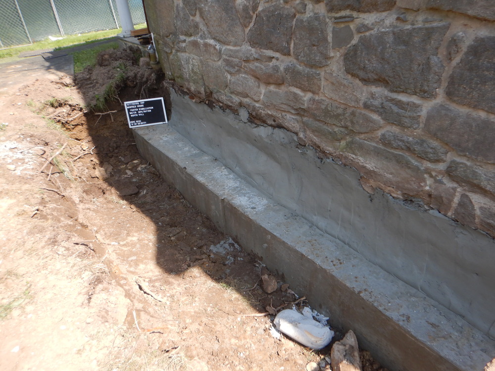
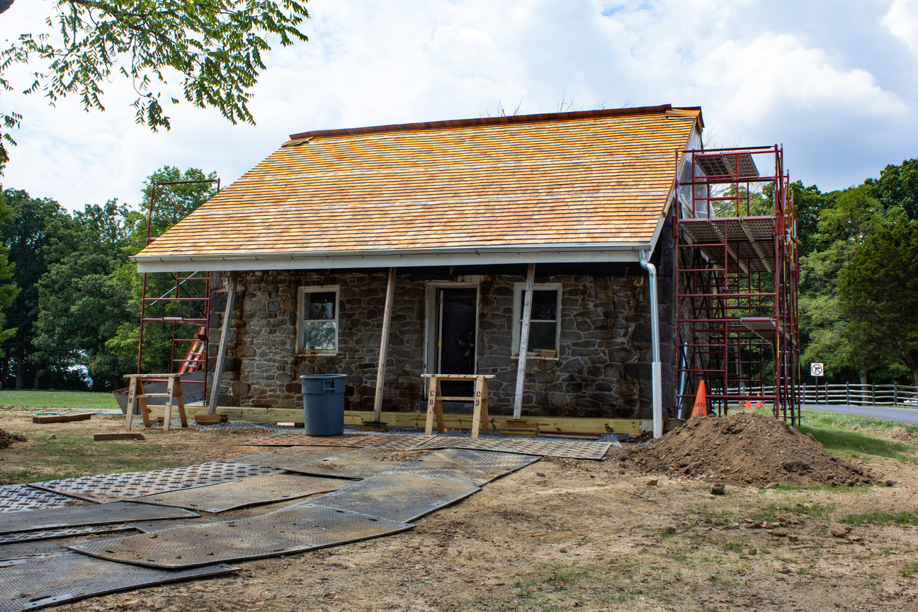
Actual work stage: inspect the wall before water-control layers conceal itNPS Photo, James Warfield House rehabilitation, Gettysburg National Military Park, 2 June 2020. Official photograph and rights record. NPS identifies this as preparation before waterproofing; public domain. Published medium-size photograph retained unchanged and uncropped. Historic-building work, not a DLG project or a standard detail for a new house.
The exposed wall base makes the sequence easier to understand: recording the existing substrate and repairs is a different task from recording the water-control layers that follow. A smooth repaired face does not establish that waterproofing, a drainage layer or a functioning outlet has been installed. No completed drain pipe is identified in this photograph.
Take three records to the review:
Before covering the substrate: identify the wall condition and repairs, and ask the responsible designer which preparation record is needed for the selected water-control system.
Before backfill: ask for photographs and product references for the selected wall layers, junctions, any perimeter drain, access points and its receiving route. Match them to the agreed drawing rather than to this historic example.
At handover: obtain the actual route and access record, any specified test or inspection results, and responsibility for cleaning, pumps or alarms where those form part of the design.
Use the role section above to distinguish the parts. The photograph supplies real work-stage context; it does not specify excavation support, structural repairs, membrane selection, pipe geometry or discharge approval.
Closer look: two real drainage work stages
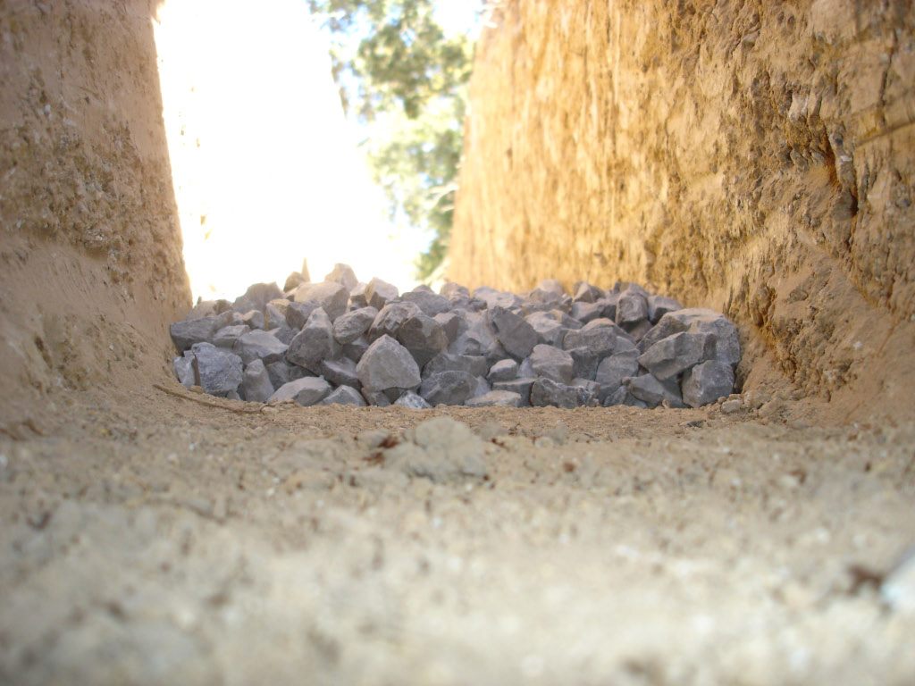
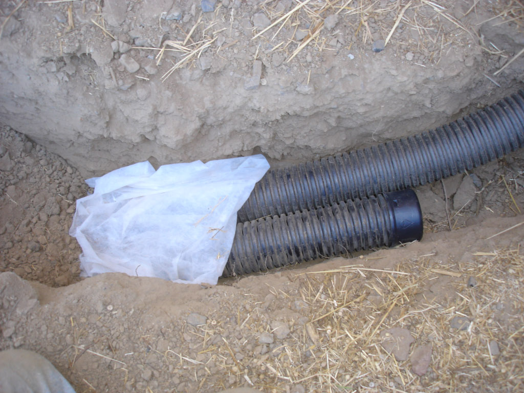
Use these historical construction references to ask what will be recorded before the trench is covered.
Open trench and stone. The photograph shows the work before covering. Ask which drawing defines the trench, bedding and receiving route for your project. Photo: Scooter133 · original upload 3 July 2007 · source and public-domain dedication.Pipework and visible fabric. Ask how pipe identification, connections and the filter arrangement will be documented before concealment. Photo: Scooter133 · original upload 3 July 2007 · source and public-domain dedication.
Original photographs unchanged. They do not establish a completed filter envelope, pipe slope, perforation orientation, discharge location or a foundation-wall connection. These are historical trench references, not a recommended assembly, a specification or a DLG project. The building-perimeter drainage detail still requires its own evidence.
02 / Deck, paving and plantingChapters 3–5 · Real application photographs, source sections and landscape roles.
3. Choose paving as an assembly
Compare finish, support, edges, transitions, drainage and maintenance as one scope. Ask for the selected manufacturer’s applicable installation and care documents, alongside the designer’s site-specific requirements.
On a narrow screen, scroll the comparison table horizontally.
Surface family
Useful comparison
Detail to resolve before ordering
Conventional concrete or bonded paving
Appearance, joints, repair approach, weather exposure and use
Levels, movement, support and runoff route
Modular pavers
Replaceable units and joint appearance
Base, restraint, joint system and threshold transitions
Permeable interlocking paving
Whole-system water route and maintenance access
Open joints, bedding, reservoir and designed soil/outlet arrangement
Loose aggregate
Intended traffic, containment and upkeep
Migration, edges, equipment movement and accessible-route suitability
Exterior timber or composite deck
Product exposure rating, finish and service access
Structure, fixings, ventilation and locally applicable approvals
Fairfax County describes permeable paving as a surface with underlying bedding and aggregate storage; systems can use full, partial or no infiltration into the soil. In permeable interlocking concrete paving, water passes through the joints. Soil, slope, groundwater and surrounding uses affect design. Sediment control and appropriate maintenance matter. [LW04]
Do not classify a pictured terrace as permeable from its appearance. A conventional paver on an unsuitable base does not become a functioning water-management system because its joints look open.
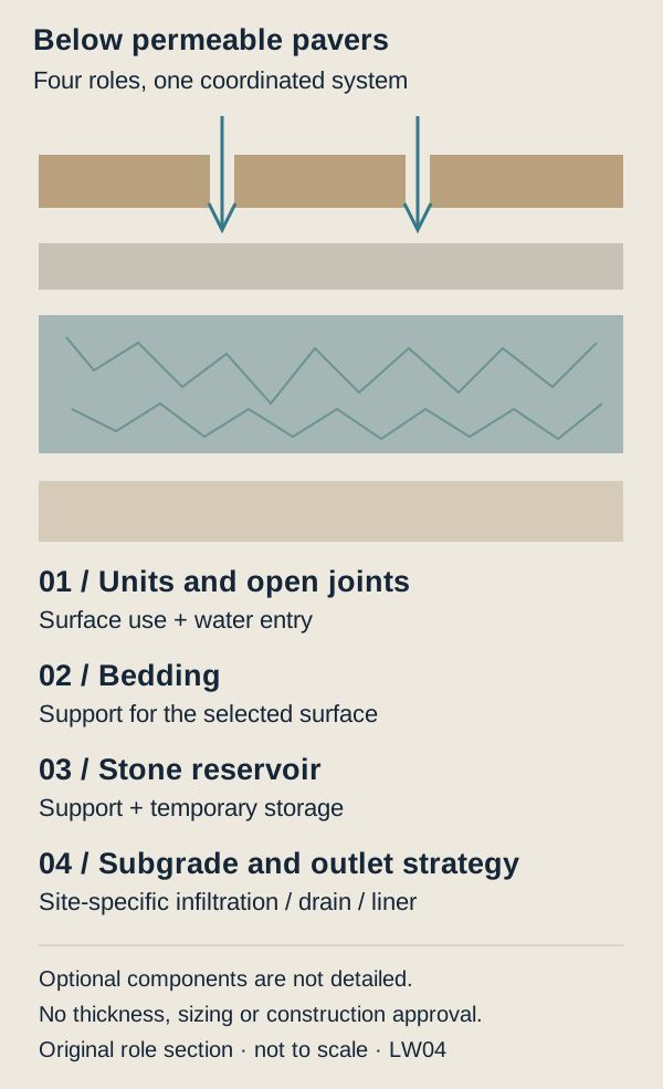
Look closer: the roles below permeable pavers
Original educational section informed by LW04. Layers have separate jobs. Thicknesses, stone grades, liner use, edge restraints, underdrain and outlet design require the selected system and site assessment. Not to scale; not a construction detail.
At doors, steps and changes of material, request a coordinated junction drawing. Verify the route’s required accessibility and the selected finish’s suitability for wet conditions and the local winter-maintenance method.
Timber deck meeting the garden
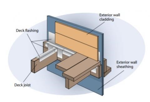
Application detail: deck-to-wall flashing rolesSource drawing, not a site photograph. FEMA’s wildfire guidance illustrates the wall/deck interface. Use it to ask how water-control layers and the selected house connection are coordinated. This diagram supplies no project-specific fastener, load, dimension or local-code approval. FEMA / Courtesy of the U.S. Department of Energy · Source record · BASC reuse guidance. Original image unchanged. Reference only; not a DLG project or an endorsement.
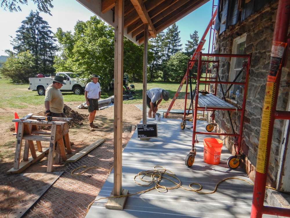
ACTUAL WORK / SURFACE STAGE
NPS Photo · James Warfield House, Gettysburg National Military Park, Pennsylvania · 18 August 2020. Official asset record · Public-domain rights record. Published NPS medium image unchanged and uncropped. Historic covered-porch rehabilitation; not a DLG project.
Read the visible interfaces. The boards meet a stone wall, timber posts and an unfinished ground approach. The source identifies installed tongue-and-groove boards and priming in progress. This is a work stage, rather than a completed landscape handover. A covered porch with this board profile is a different exposure and assembly from an open, spaced-board garden deck.
Compare the same project at two dates:14 August: porch replacement and temporary support; 18 August: boards installed and priming underway. The photographs help explain the sequence. Neither date proves hidden connections, wall flashing, final soil clearance or drainage performance.
Use the photo when comparing quotations: ask for a drawing of the selected wall and post interfaces, a record of the supporting frame before boards conceal it, and a separate detail showing the final ground level and water route. Identify who checks those records and which items remain open at handover.
Read this junction in three layers: the walking surface, the supporting frame and the ground below. Ask how water passing between boards leaves the area, how soil or mulch is kept from accumulating against vulnerable members, and how the underside remains accessible for inspection. A gravel margin is not itself proof of a working drain.
The American Wood Council’s DCA6 distinguishes above-ground and ground-contact material uses and illustrates water protection at house connections. [LW12] It is a guide based on the 2015 IRC, not confirmation of today’s adopted local code. For an actual deck, establish the selected wood/product, exposure, support, fasteners, clearances and any house connection with the designer and authority. A freestanding deck, a house-attached deck and a deck over waterproofed occupied space require different details; the image does not combine them.
Worked deck-board quantity: why area alone can mislead
Assume a 12 ft-wide by 14 ft-long deck, with boards running along the 14 ft direction. For this geometry exercise use a 5.5 in board face, a 0.25 in gap between boards and a 0.25 in edge allowance at each side. Gap and edge allowances are editorial inputs, not Trex installation requirements.
On a narrow screen, scroll the comparison table horizontally.
Step
Exercise calculation
Board rows
25 × 5.5 + 24 × 0.25 + 2 × 0.25 = 144 in = 12 ft
Continuous board runs
25 runs, each 14 ft long
Assumed stock length
One 16 ft board per run → 25 stock boards before spares
Idealized length offcut
25 × (16 − 14) = 50 linear ft before saw cuts/end trimming
Trex’s professional product page lists Enhance boards at 5.5 in wide with 16 ft among its lengths. [LW17] Only that dimensional context is drawn from the manufacturer. The row layout, allowances and cutting arithmetic are original assumptions. Actual product gapping, support, fixing, perimeter, butt-joint and end-trimming requirements must be coordinated before ordering.
The deck area is 168 sq ft. Dividing only by the face area of a 16 ft board gives 168 ÷ (16 × 5.5 ÷ 12) ≈ 22.91, or 23 boards rounded up. That shortcut misses the assumed continuous-run layout requiring 25 boards. A supplier may reduce waste with another layout, but joints and supports then need their own detail. This is why a quoted deck area is not a complete board list.
Ask separately about frame/support, foundations, fasteners, fascia, stairs/guards if applicable, house connection/water protection, waste/spares and inspection. No structural member sizes, spans or foundation quantities are derived from this board-face exercise.
Concrete terrace meeting soil
Here, “concrete deck” means an exterior slab-on-ground terrace, not an elevated structural concrete deck. Its design needs the finished levels, supporting ground/base, edge treatment, movement-joint strategy and surface-water route to be coordinated. Do not assume the adjacent soil will accept every storm or that every edge needs a buried perforated pipe.
NRMCA distinguishes contraction, isolation and construction joints in slabs on grade. [LW13] A surface groove is not automatically a drainage channel; where the terrace meets an existing building or other restraint, ask which joint and water-control detail applies. An abrupt edge beside a walking route also needs an access and fall-risk review. No slab thickness, reinforcement, universal slope or joint spacing is prescribed here.
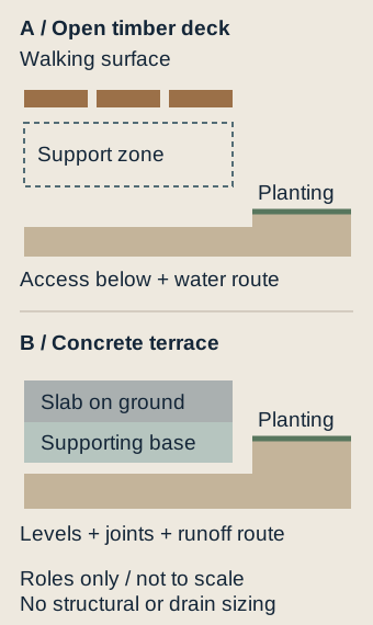
COMPARE THE JUNCTION / BEFORE IT IS COVERED
Read the edge, then ask for the hidden detail.
Original DLG role sections. Not to scale. Soil height is illustrative; it is not a clearance, support or drainage specification. An elevated concrete deck or waterproofed roof terrace needs a different assembly.
01 / Timber and the ground
Read the exposed porch frame photograph and the board-installation photograph as two work stages. For an open deck, request the actual exposure rating, ground relationship, inspection access and route for water below the boards. The historic covered porch does not establish these details.
02 / Concrete and the building
Ask the drawing to identify movement joints, building/threshold interfaces, finished levels and the receiving runoff route. NRMCA distinguishes joints for crack control, separation and construction sequence [LW13]. Those roles are different from a surface drainage channel.
03 / Ground and the foundation
Compare the real foundation drainage-layer photograph with the surface edge. Ask for separately identified roof, surface and foundation-water routes, including full-tank or blocked-inlet conditions. A gravel strip alone does not document a receiving outlet.
Before concealment: request the agreed junction drawing, selected product references, dated photographs of hidden layers and the responsible reviewer’s inspection record. At handover, retain the actual access/outlet route and maintenance responsibilities. These are proposal-review questions; the project designer and authority determine the required details and inspections.
Linear surface drainage within paving
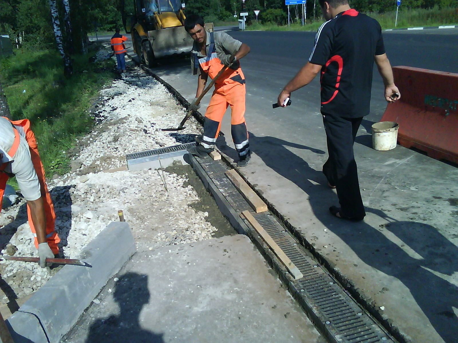
A surface channel receives water at the paved surface and conveys it through a designed system. It is different from a subsurface land drain and from the foundation drainage system. Establish the catchment and rainfall design basis, finished levels, grate/load/access requirements, support and outlet before selecting the visible cover.
Closer look: read the channel and its surrounding works together
Read the channel and its surrounding works together
A roadside channel installation reference, not a residential terrace or the NDS system in this guide. It shows a grate and surrounding construction before completion; it does not establish the outlet, support dimensions, load class or acceptance of the work.
What to ask: Does the quoted scope include the support, paving junction, outlet connection, clean-out access and inspection before concealment?Photo: Belt777 · 2008 · Wikimedia Commons source · CC BY-SA 3.0. Original image unchanged and uncropped. Source and licence reviewed 20 October 2026. Not a DLG project or an endorsed installation.
For a real product-specific example, see the NDS 8-inch Pro Series paver installation detail. The manufacturer’s sheet shows channel/grate, concrete encasement, paving/base layers and load-dependent provisions. [LW14] Those dimensions and products are not transferred to our generic photo or treated as a recommendation for this garden.
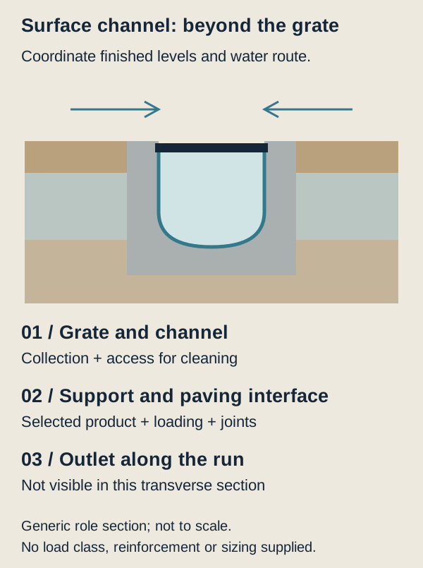
Look closer: channel, pavement support and outlet
Original educational role section informed by the NDS sheet, not a reproduction of its installation drawing. A transverse section cannot establish the channel’s longitudinal fall, outlet or receiving-point capacity. Use the selected manufacturer’s current detail and site design.
Review sequence: confirm receiving route and permission; set out coordinated levels; prepare the selected support and outlet; inspect connections before concealment; finish the paving junction and retain grate access; commission using the approved method. Record any sediment trap and cleaning access specified for the selected system. Do not connect roof, surface and foundation water into an unknown pipe.
Worked surface-water example: levels, volume and flow are different
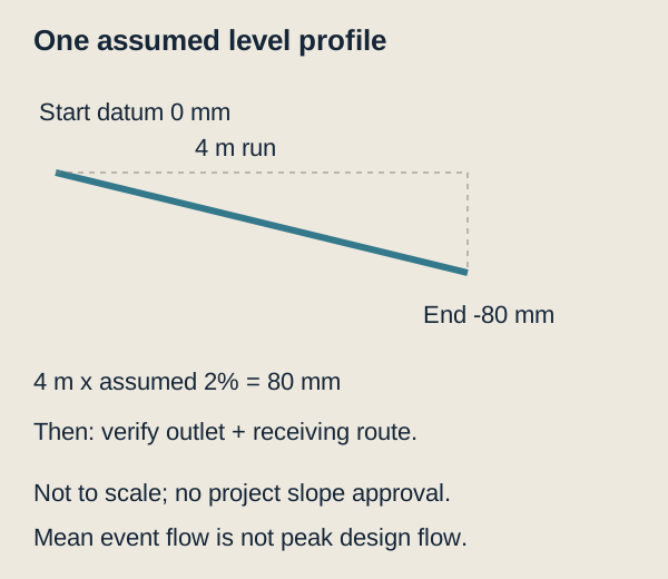
Assume a 6 × 4 m terrace, 40 mm of rain over a one-hour exercise event and an assumed runoff coefficient of 0.90. These are original teaching inputs, not rainfall design data for Boston, NOVA or Atlanta.
On a narrow screen, scroll the comparison table horizontally.
Quantity
Calculation
Exercise result
Catchment face
6 × 4
24 m²
Event runoff
24 × 40 × 0.90
864 L
Mean inflow across the assumed hour
864 ÷ 3,600
0.24 L/s
Assumed level fall over a 4 m route
4 × 0.02
0.08 m / 80 mm
The 2% fall is an illustrative geometry input, not a universal paving or accessibility rule. The 0.24 L/s is an event-average flow, not the peak design flow and not evidence that a chosen grate/channel/pipe is adequate. The example excludes other roof or paved catchments. An actual design needs relevant rainfall intensity and duration, levels, inlet interception, conveyance, receiving capacity and an overflow route.
Read the assumed level profile and receiving route
Original arithmetic profile, not to scale. No door clearance, accessible slope, drain capacity, foundation level or permitted discharge is established.
Ask a provider to show the starting/ending levels and explain the design flow. A channel named only by its visible width leaves unanswered whether water can enter, travel through and leave the system. A full tank or blocked grate must also have an agreed response; connecting it to the footing drain is not an assumed solution.
Read a named detail: the NDS 8-inch Pro Series paver sheet separates Class A pedestrian and Class B configurations, with different supporting details and notes. [LW14] It is an installation/support reference, not a hydraulic capacity calculation. A quotation should name the selected load/use configuration, channel/grate, support, outlet and receiving route; an “8-inch drain included” line does not resolve them.
Building perimeter: identify the complete water-control route
For a basement-type foundation, the Building America footing-drain guide describes the drain, washed stone/filter arrangement and a defined discharge or sump route. [LW15] Use the original perimeter section above to distinguish that below-grade system from a shallow terrace inlet and from roof-water discharge. Existing foundation work also needs an investigation of the cause and a professional excavation/support plan; the exercise here supplies no digging sequence.
Ask for a section that identifies the actual wall water-control layer, drainage path, filter/soil interface, footing relationship, inspection/access points and the accepted outlet. A quote for “pipe plus gravel” leaves the wall interface and discharge unresolved. Before backfill or concealment, agree which measurements, photographs and authority/designer checks will be retained. A photograph of a pipe alone is not evidence of the complete route.
For boundary materials, post/ground relationships, slopes and gates, continue with the companion Modern Fences & Gates guide. For fire-feature materials, terrace interfaces, drainage, ventilation and service access, see the companion Modern Fire Features guide.
4. Match planting and irrigation to the site
Make a zone schedule before selecting an irrigation controller. Separate areas with different exposure, soil, plant needs or establishment stages. Select species with local advice; a generic illustration cannot identify a suitable plant palette for Massachusetts, Northern Virginia or another region.
For each zone, record its area, plants, sun, soil, delivery method and person responsible for adjustment. Consider mature size and access around equipment, paths and building openings. Establishment watering and long-term maintenance are different tasks.
EPA watering guidance distinguishes weather-based and soil-moisture-based controls and describes microirrigation at plant roots. It recommends seasonal adjustment, correcting overspray and inspecting for leaks or blocked components. [LW02] A connected controller still needs a correctly designed and maintained system.
Ask the irrigation provider to confirm source pressure and flow, simultaneous zone demand, filtration and regulation, backflow protection and local water restrictions. Do not infer pipe size, pump power or runtime from garden area alone.
Link any connected controller to the Smart & Connected Homes checklist: identify local operation, internet dependencies, manual control, support and account handover. Keep valves, filters and isolation points accessible.
Coordinate outdoor lighting and services
Define which entrances, level changes, paths and service points need lighting, and when. Review glare from neighbouring property and inside the home; compare the actual fittings’ suitability for their exposure and intended location. Ask for the control, override and maintenance approach rather than selecting fixtures from a mood image alone.
Coordinate cable and pipe routes before final paving. Have the relevant professional determine equipment, protection, installation and any electrical approval. The Landscape register records responsibilities; it does not prescribe electrical sizing or a wiring method. Fairfax’s permit guide treats electrical scope separately from site and building review. [LW08]
5. Give rain gardens a defined role
A rain garden is one possible way to manage suitable runoff near its source. Northern Virginia’s conservation district provides guidance on rain gardens and other residential low-impact practices, while noting that performance can degrade through poor design, construction or maintenance. [LW05]
Ask what area feeds the feature, how the soil was assessed, what storage and drawdown are intended, how overflow leaves and who maintains the inlet and planting. Where infiltration is unsuitable, the answer may be another practice or a different location.
A low patch of lawn is not automatically a rain garden. Avoid assigning a depression a stormwater function without checking the soil, groundwater, utilities, building relationships and receiving route. Do not use an illustrative planted area to promise flood prevention.
03 / Water collection and the project fileChapters 6–10 · Roof-water arithmetic, approvals, sequence and maintenance.
6. Connect collection, storage, use and overflow
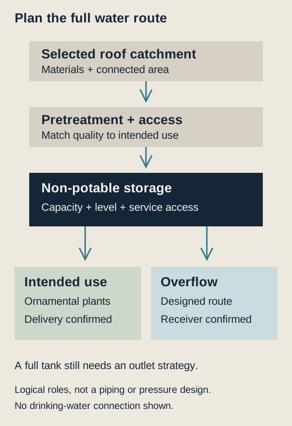
For a proposed rainwater system, document the contributing roof area and materials, debris sources, pretreatment, storage, intended use, delivery arrangement and overflow. Access for cleaning and replacement belongs in the layout from the start.
CDC explains that apparently clean rainwater may contain germs and chemicals. It recommends limiting exposure, keeping rainwater separate from drinking-water pipes, maintaining the system and considering screens and first-flush diversion. Watering non-edible plants is one lower-exposure use; edible plants and indoor uses need separate advice. [LW06]
This guide’s example is non-potable water for ornamental planting only. It does not propose drinking, cooking, washing food, edible-crop irrigation or an indoor plumbing connection. A screen or first-flush device alone does not establish drinking-water quality.
Original system-role diagram. A full tank still needs a suitable overflow route. Arrows show relationships, not pipe sizes, pressure or an approved discharge connection. Treatment and delivery must match the intended use.
Check collection rules and applicable plumbing, site and health requirements with the relevant authorities. DOE’s alternative-water tool provides state-level planning resources; it is not a property-specific permit determination. Its monthly rainfall context cannot resolve the timing of individual storms and dry periods. [LW07]
7. A worked example: roof water is not tank capacity
Consider a hypothetical home with a 100 m² horizontal roof catchment, 1,000 L of usable tank storage and 80 m² of ornamental planting. Use an invented 25 mm storm and a planning collection factor of 0.80. These are arithmetic assumptions, not measured local rainfall, an established collection efficiency or a tank recommendation.
One millimetre of rain over one square metre equals one litre. Use the horizontal contributing area, not the sloping material area or the entire roof if only some downspouts feed the tank.
On a narrow screen, scroll the comparison table horizontally.
Step
Calculation
Meaning
Rain falling on contributing roof
100 m² × 25 mm = 2,500 L
Gross event volume
Assumed volume reaching tank
2,500 L × 0.80 = 2,000 L
Simplified allowance for collection losses
Empty tank, no withdrawal during storm
min(2,000 L, 1,000 L) = 1,000 L stored
The other 1,000 L needs an overflow route
Tank initially holding 600 L
Free capacity = 400 L
Event overflow becomes 1,600 L, assuming no withdrawal
Illustrative net planting requirement
80 m² × 10 mm = 800 L
Hypothetical water requirement after accounting for rainfall; not horticultural advice
Assumed delivery efficiency
800 L ÷ 0.90 ≈ 889 L withdrawn
A separate illustrative application-loss assumption
Usable full-tank comparison
1,000 L ÷ (800 L ÷ 0.90) = 1.125 applications
One complete assumed application, with about 111 L remaining; not a schedule or performance prediction
Capacity boundary: this example assumes 1,000 L is available for use; the product’s nominal volume is unspecified. Inlet/overflow levels, inaccessible water and equipment limits may make usable capacity smaller than the nominal rating. Keep full precision in the calculation: the assumed draw is 888.888… L, shown as 889 L only for reading.
Volume and arrival rate answer different questions. The paired 10-minute and 60-minute rainwater example uses the same 100 m² roof, 25 mm rain and initially 600 L tank. Overflow totals 1,600 L in both cases, but equivalent inflow is 200 versus 33.3 L/min. These invented events explain the distinction; they do not size the site’s drains. This page’s 80 m² planting / 0.90 delivery exercise is separate from the rainwater guide’s 100 m² planting / 0.85 exercise.
The 0.80 collection factor and 0.90 application efficiency represent different losses; do not apply both to the roof volume. Real calculations must handle first-flush losses consistently and avoid counting them twice.
The example does not establish how many days the garden can be supplied. That requires actual seasonal plant demand, rain timing, usable tank volume and operation. A tank may overflow during a wet week and be empty during a later dry period. Annual rainfall totals cannot show those events.
For selection, request a dated water balance using appropriate local rainfall data, demand assumptions, initial storage and overflow. Compare more than one capacity and include maintenance, access and installed cost. Keep any claimed water-bill benefit separate from system volume.
8. Confirm approvals before excavation
Use the actual property jurisdiction, not its postal city alone. Establish which authority handles site work, buildings, plumbing, electrical work, wetlands, tree protection and the receiving drainage system. Record written responses and the version of plans reviewed.
On a narrow screen, scroll the comparison table horizontally.
Local example
What the official guidance establishes
What remains project-specific
Fairfax County, Virginia
Building, trade and land-disturbance approvals depend on scope. Listed on-grade patios may still need site, zoning or other approvals. [LW08]
Actual work classification, disturbance, easements, protected areas and discharge
Fairfax County site work
Clearing, grading, excavation and changes to runoff can fall within land-disturbance review; the county provides its own calculation guidance. [LW09]
Exemptions, total work/access/stockpile area and applicable plan requirements
Plainville, Massachusetts
The Conservation Commission advises contacting it before relevant landscaping, clearing or excavation near wetland/floodplain/stream resources. [LW11]
Resource boundaries, local bylaw, application and required permission; other towns have their own review
The Plainville example is not a statewide landscaping-permit rule. Fairfax County requirements are not automatically those of the independent City of Fairfax. No exemption, permit fee or approval duration is assumed here.
Before digging, follow the applicable state notification and response process. Virginia 811 explains that it notifies participating utility owners; private-line owners must arrange location of their own lines. [LW10] Include private irrigation, outbuilding services and other known private systems in the investigation. Use current state instructions for notice periods and excavation methods.
Prepare the project file
Address, parcel, ownership/association authority, boundary and easement information.
Existing-condition survey or plan at the accuracy required for the work; dated rain and condition photographs.
Proposed levels, surface areas, drainage/overflow receiving route and erosion-control approach.
Soil/infiltration investigation and relevant tree, well, septic or protected-resource records.
Selected product/system documents; tank, irrigation, structural or electrical details where applicable.
Utility notification and response records plus private-location evidence; contractor scope and insurance/licensing checks as applicable.
This is a preparation index. The relevant authority determines the actual submission requirements.
9. Sequence the work around decisions and inspections
Investigate. Confirm records, levels, existing problems and areas needing specialist assessment.
Coordinate the concept. Resolve circulation, planting, water routes, service access and potential downstream effects together.
Confirm the approval path. Identify submissions and permissions before committing to excavation or non-returnable materials.
Compare like-for-like scopes. Include enabling works, spoil removal, erosion controls, plant establishment and reinstatement.
Prepare the site. Complete applicable utility processes and install protection for retained features and drainage systems.
Inspect work before concealment. Record levels, selected assembly, buried services and required authority/designer acceptance before covering.
Commission and establish. Demonstrate controls, isolation, delivery and the selected system’s overflow/testing procedure; document observations and open issues.
Hand over. Provide as-built records, care instructions, warranties, accounts and an establishment/maintenance responsibility schedule.
This is an illustrative project sequence, not a universal construction method. The designer and authority set the actual inspection hold points. Avoid an improvised flooding test or connection to an unverified drain.
Actual work stage: coordinate a porch renewal before the finish hides the frameNPS photo, James Warfield House rehabilitation, Gettysburg National Military Park, 14 August 2020. Official photograph and rights record. NPS describes temporary shoring during porch deck and post replacement; public domain. Published medium-size photograph unchanged and uncropped. Historic porch work, not a modern deck specification or a DLG project.
A finished board sample describes only one part of this scope. In this work-stage view, the roof above, the porch structure and the ground approach have to be considered together. The temporary works belong to this project; their arrangement is not an instruction to reproduce.
Ask the team to show: which existing members are retained, what supports the roof during replacement, who resolves the final structure and connections, and how the finished ground and water route meet the porch. Keep the temporary-works responsibility separate from the permanent deck scope.
For quotation comparison, request the same list from each bidder: removal and protection, investigations and repairs, temporary works where needed, permanent frame, boards, steps/guards where applicable, service access and ground reinstatement. A price for boards alone cannot explain those responsibilities.
Photo acceptance boundary: the wide view does not verify a ledger flashing, fastener schedule, foundation depth or a finished deck-to-soil junction. Those details still need the selected assembly and a closer project record.
10. Compare the whole cost and keep it maintainable
AFTER INSTALLATION / NAME THE SYSTEM FIRST
A care plan belongs to the selected assembly.
Timber + finish
Record the wood, treatment and coating actually installed. Ask for compatible cleaning and recoating instructions, condition checks and access to the frame. A finish-maintenance visit and a structural inspection are separate responsibilities.
Keep the exact product line and care-guide version. Trex separates newer lines from early-generation composites; pressure washing is not recommended for the latter. [LW18] Do not transfer a method from one product generation to another.
Record the finish, any coating or sealer, and the agreed joint-care instructions. Identify who reviews new cracks, edge movement or persistent ponding. Cleaning the surface does not confirm that concealed support or water routes are performing.
Keep sediment and maintenance access in the plan. Fairfax’s guidance calls for vacuum sweeping at least twice yearly and lists practices to avoid, including power washing. [LW04] This is a named local source example; confirm the selected system’s actual maintenance plan.
Write the responsibility, not just “maintain as required”. Record the task, applicable instruction, interval or event trigger, access/equipment, named person and evidence of completion. Costs and frequencies remain open until the actual system and scope are agreed.
Blank planning worksheet · Print or save as PDF from your browser, then complete it on paper or in a suitable PDF editor. The page does not save entered project information or submit it to DLG. No project has been inspected or accepted through this template.
Request separate prices for survey/design, applications, ground preparation, buried infrastructure, surfaces, planting, irrigation, rainwater equipment, commissioning and reinstatement. Identify exclusions, provisional quantities, disposal, access restrictions and what happens if unsuitable soil or unknown services are found.
Add recurring responsibilities: vegetation establishment, filters and inlets, sediment removal, paving care, pump/controller service and winter preparation appropriate to the location and system. Use manufacturer, designer and authority instructions for intervals; do not assume one calendar fits every system.
Ask the provider:
Where does the water go during ordinary use, overflow and blockage?
Which observations and tests support the selected infiltration or outlet strategy?
Which assembly details and inspections must be accepted before covering work?
Who supplies establishment care, replaces failed plants and demonstrates the irrigation zones?
Which access points, drawings and operating records will the owner receive?
Compare outdoor proposals through their missing interfaces
On a narrow screen, scroll the comparison table horizontally.
Fictional scope
Clarification before choosing a firm
“Build 168 sq ft deck”
Board layout, structural responsibility, edge/house details, approvals and what the area-based price excludes
“Install channel drain”
Catchment and design-flow basis, finished levels, load configuration, outlet and accepted receiving route
“Waterproof foundation and add drain”
Cause investigation, existing structure/excavation responsibility, complete wall/filter/drain section, discharge and concealed-work records
Request comparable drawings, component identities and variation rules from each bidder. A detailed quote is easier to compare, but still needs suitable experience references and applicable credential/insurance checks. Establish who will demonstrate flow/access and hand over as-built routes and maintenance information. No fictional scope is a real firm rating or a project quotation.
The companion project register provides blank fields for those answers. No installed price, saving, property-value increase or flood-protection guarantee is inferred from the concept image or worked arithmetic.
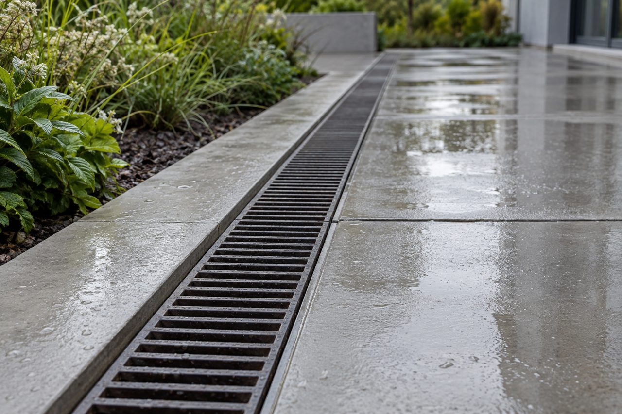
Optional architectural concept illustrationsChannel-grate appearance concept — AI-generated
Application appearance: an accessible grate and its pavement interface. AI-generated generic concept, not the NDS product in the source drawing. Wetness does not prove slope, hydraulic capacity or a functioning downstream connection.
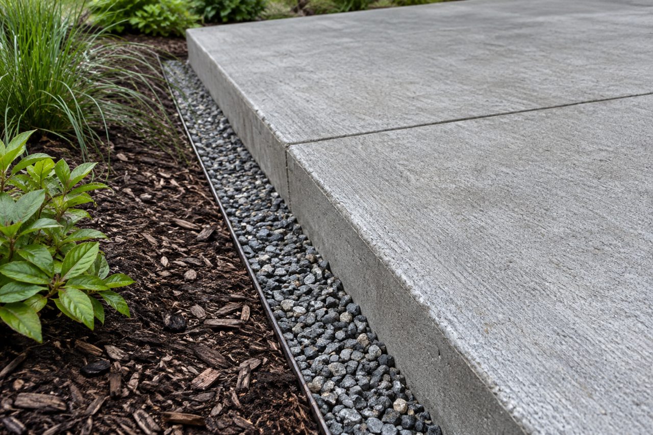
Concrete-to-soil appearance concept — AI-generated
Application appearance: concrete edge, planted-ground level and a maintenance margin. AI-generated concept; the apparent height is not an accessibility, slab-thickness or drainage specification. The gravel is not shown as a designed infiltration trench.
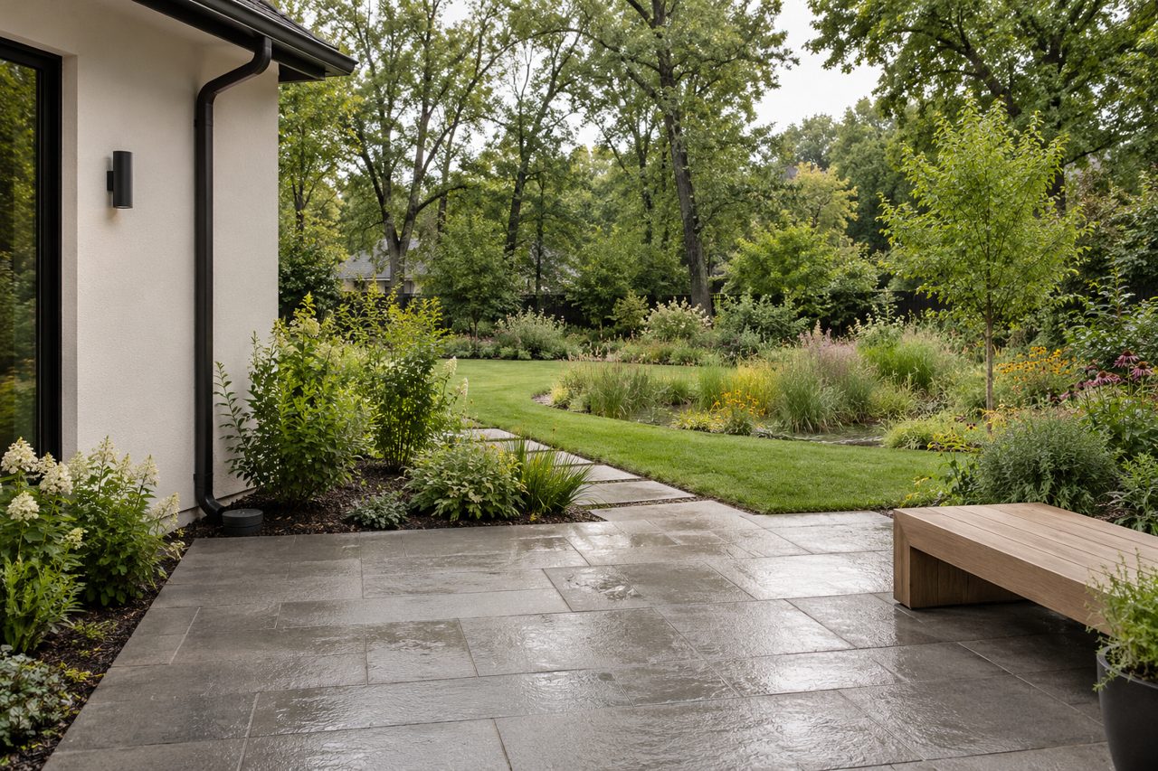
Garden arrangement concept — AI-generated
A restrained garden can combine a usable terrace, planting and space for water management. AI-generated architectural concept, not a completed DLG project. Hidden drainage, plant species, paving permeability and construction suitability cannot be verified from this image.
Deck-edge appearance concept — AI-generated
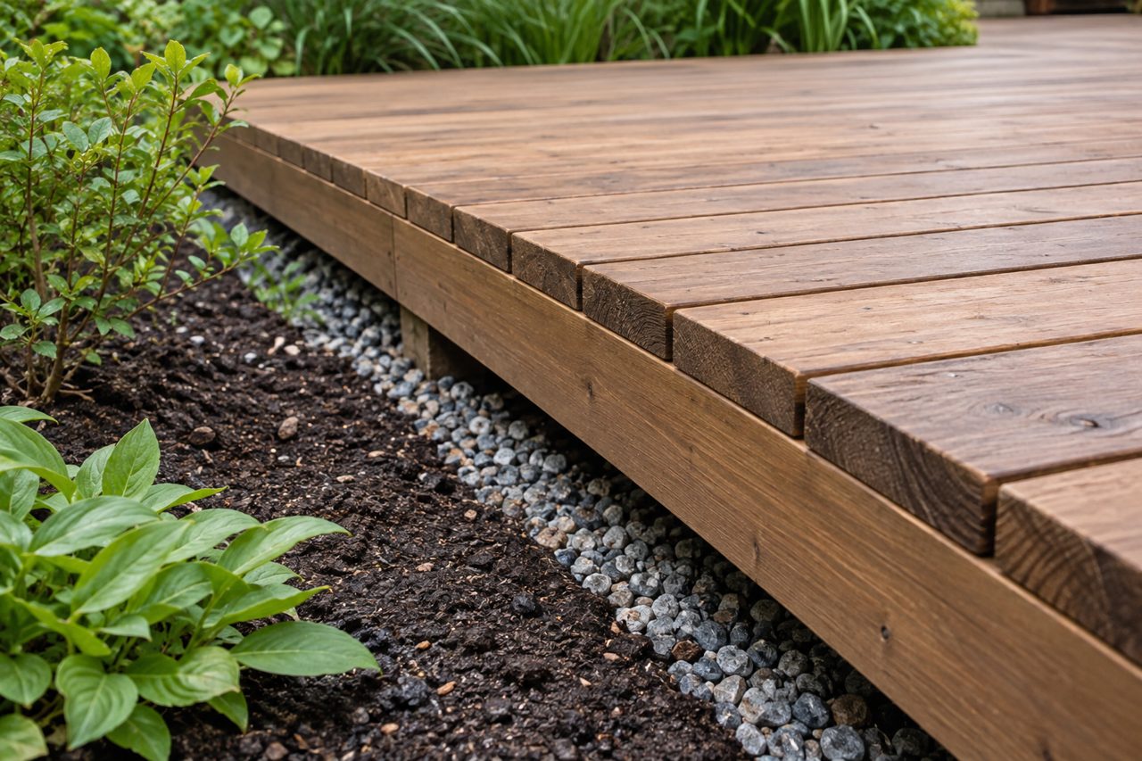
Application appearance: board joints, exposed edge and separation from planting. AI-generated concept, not an inspected deck. Visible support fragments, clearance and board spacing are illustrative and must not be copied as a structural detail.
Sources, calculations and review dates
This guide brings landscape planning together with the existing Rainwater, Drainage, Storage & Reuse series. Its examples support a project brief; they do not establish a surveyed layout, a drainage design or permission to build.
A useful outdoor space begins with daily life, the existing land and a clear route for water. Plan those relationships before choosing the paving, plants or tank.
Sources and scope
Original sources checked 19 October 2026; LW14–15 and new LW17 reviewed for selected additions 20 October 2026. Other earlier claims were not all rechecked this turn. Source statements support the identified planning principles; examples, tables and questions are DLG editorial synthesis. No source certifies the generated scene or supplies this property’s design.
Junction review · 28 October 2026: the AWC DCA6 PDF and NRMCA CIP 6 PDF were re-opened for the material/exposure, house-interface and joint-role discussion. DCA6 remains explicitly a 2015 IRC-based historical reference, not evidence of local adoption. The new edge comparison is an original educational drawing; existing photographs retain their separate source and use records. Deck-board arithmetic was independently checked: 25 rows occupy 144 in with the stated gaps/edge allowances; 25 × 16 ft stock gives 50 linear ft of idealized offcut before saw cuts or end trimming. This quantity exercise does not size the structure or select product installation gaps.
LW01 · EPA — Landscaping Tips. Site/plant conditions, hydrozones and establishment. Open LW01 source
LW02 · EPA — Watering Tips. Control types, microirrigation, seasonal adjustment and maintenance. Dated draft-specification wording on the page is not used as current product status. Open LW02 source
LW03 · DOE Building Science Education — Final Grade Slopes Away from Foundation. General away-from-building water-routing principle; numerical construction instructions are not adopted here. Open LW03 source
LW04 · Fairfax County — Permeable Pavement. Assembly roles, infiltration alternatives and maintenance context. Open LW04 source
LW05 · Northern Virginia Soil and Water Conservation District — Rain Gardens and Low Impact Development. Practice options and design/construction/maintenance dependence. Linked manuals are further reading, not claimed as fully reviewed. Open LW05 source
LW06 · CDC — Collecting Rainwater and Your Health. Contamination, separation, exposure and system upkeep. Open LW06 source
LW07 · DOE FEMP — Alternative Water Supply Tool. Federal/commercial planning resource, catchment/storage/operation factors and monthly-data limitations; not a residential permit determination or a daily simulation. Open LW07 source
LW08 · Fairfax County — Does My Project Require a Permit? Scope-dependent and additional approvals. Open LW08 source
LW09 · Fairfax County — Land Disturbance 101. Land changes and county-specific review framework; no universal threshold adopted. Open LW09 source
LW10 · Virginia 811 — Excavator FAQ. Notification role and private utility locating responsibilities. Conflicting timing wording on this page is not reproduced; follow current applicable state/ticket instructions. Open LW10 source
LW11 · Town of Plainville — Conservation Commission. One Massachusetts municipality’s pre-work conservation contact guidance; no statewide exemption or universal buffer rule inferred. Open LW11 source
LW12 · American Wood Council — DCA6, 2015 IRC-based guide. Pages 2–3 and 13–14: material/exposure distinctions and house-connection water protection. Historical technical reference, not a statement of current locally adopted rules. Open LW12 source
LW13 · NRMCA — CIP 6, Joints in Concrete Slabs on Grade. Joint roles only; numerical prescriptions and source illustrations are not reproduced. Open LW13 source
LW14 · NDS — 8-inch Pro Series Channel Drains & Grates Pavers Installation Detail. Specific manufacturer sheet, save date 6 May 2021, visually reviewed. Reference link only; not a generic sizing rule or an endorsement. Open LW14 source
LW15 · Building America Solution Center — Footing Drain Pipe. Exterior footing-drain, filtration and receiving-route roles; source numerical details and historical code examples are not adopted. EPA training photographs remain external references. Open LW15 source
LW16 · Building America Solution Center — Below-Grade Water Management for Urban Sites. Wall waterproofing/drainage interfaces and groundwater-dependent design context, not a design for this property. Open LW16 source
Continue with the companion Renovation Permissions, Solar & Storage and Smart & Connected Homes packages when their subjects overlap. Use the related-reading links above to continue into the companion guides.
LW17 · Trex, professional decking product page. Enhance profile dimensional context only: 5.5in board width and16ft length option; layout/gaps/spares not manufacturer prescriptions. Open LW17 source
LW18 · Trex — Care and cleaning. Product-generation distinction only; no pressure, chemical or warranty prescription is transferred to another product. Open LW18 source. Rechecked 28 October 2026. LW04 was re-opened on the same date for its maintenance section; its example frequency is attributed to Fairfax, not presented as a universal interval.