
DLG GROUP · HVAC / HEATING, VENTILATION AND AIR CONDITIONING
Ventilation and heat recovery: follow the air
HVAC means Heating, Ventilation and Air Conditioning. This guide focuses on the ventilation part: air routes, recovery, building interfaces and the records behind an installation.
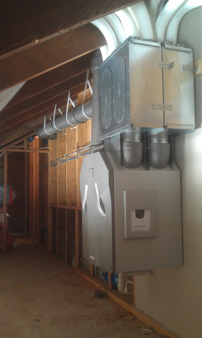
ACTUAL PHOTOGRAPH / REFERENCE
Read the equipment and the connections
- HRV cabinet: The installed unit is below the metal duct box.
- Visible duct connections: Two round connections are visible immediately above the cabinet.
- Duct routing: The ductwork continues above the equipment; the photo does not identify every air path.
Verify on site: Verify the four port functions from the duct plan or labels, and ask for measured airflow. The photo does not establish balance or performance. See the concept diagram.
One room heats up first? Check the room before sizing new AC.
The source identifies this installed unit as a heat recovery ventilator. Its visible enclosure and connections locate the equipment in the building; the photograph does not establish airflow, efficiency or commissioning.
Ask: Where are the unit, four air routes, service clearances and commissioning records identified in the actual proposal?
Photo source & use
[bundle] design studio / Courtesy of the U.S. Department of Energy. Source record · BASC reuse guidance. Resized and encoded as WebP; no retouching. Checked 27 October 2026. Reference only; no DLG project, product endorsement or approval of another installation is implied.
01 / Functions and air routesChapters 1–3 · Heating, ventilation, recovery and four connections.
1. Give each function a job
HVAC means Heating, Ventilation and Air Conditioning. The ventilation brief identifies how outdoor air is supplied and indoor air is removed. DOE's whole-house ventilation overview distinguishes exhaust, supply, balanced and energy-recovery arrangements. [V01] Record the actual proposed arrangement before comparing boxes or brand names.
| Function | What the proposal should establish | What remains a separate question |
|---|---|---|
| Heating / cooling | Room loads, equipment output, distribution and comfort controls. | Which designed route supplies outdoor air? |
| Whole-house ventilation | Outdoor intake, room supply, extract paths and exhaust termination. | How are local cooking/bathroom exhaust and pressure effects coordinated? |
| Filtration | Selected filter, airflow/pressure allowance, access and replacement. | What ventilation and source-control functions are still needed? |
| Humidity management | Moisture transfer, any active removal equipment and the operating limits. | Which functions are included in the actual equipment rather than implied by a label? |
A PNNL multifamily example explicitly separates an ERV, room conditioning, local kitchen exhaust and supplemental dehumidification. It illustrates roles; its duct arrangement and code references are not a ready-made design for a detached house. [V06]
2. HRV and ERV: what is recovered?
HRV — Heat Recovery Ventilator: recovers heat between the outgoing and incoming streams. ERV — Energy Recovery Ventilator: also transfers moisture through its selected recovery process. PNNL describes this distinction and both dedicated-duct and central-air-system arrangements. [V02]
| Review subject | HRV proposal | ERV proposal |
|---|---|---|
| Recovery role | Identify heat recovery and its rated conditions. | Identify heat and moisture transfer separately. |
| Climate and occupancy | Ask how winter moisture, outdoor conditions and occupancy informed selection. | Ask which seasonal humidity conditions support the proposed moisture-transfer behaviour. |
| Cold operation | Request the selected model's frost/defrost sequence and its effect on delivered ventilation. | Request the actual operating limits; do not assume every ERV is frost-free. |
| Humidity outcome | Ask whether any additional humidity-control equipment is needed. | Ask whether active dehumidification is still required; moisture recovery is not itself a room-humidity guarantee. |
| Maintenance | Identify filter/core care, drainage where required and service access. | Identify the exact core/filter procedures; do not copy another model's cleaning method. |
Choose against the site's weather, occupancy, envelope and equipment data, then document the decision. “HRV for every cold place” or “ERV for every humid place” is too little information for the proposal review. The equipment manual and design should identify the real operating limits.
3. Trace all four air connections
Follow four air paths
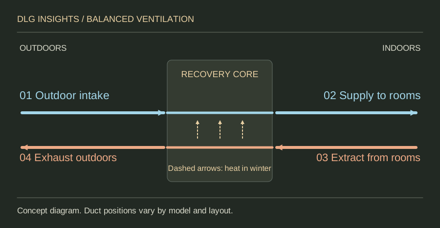
HRV: transfers heat. ERV: transfers heat and some water vapor. Neither replaces the equipment that heats or cools the house.
At a home showing: Ask which two hoods are intake and exhaust, which rooms are supplied or extracted, and whether there is a measured airflow report. See the commissioning questions.
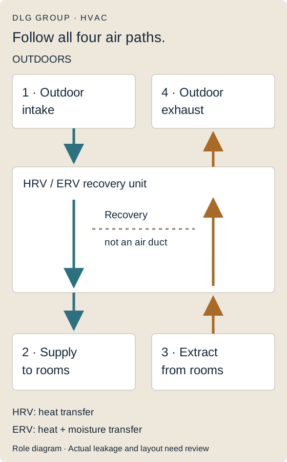
- Outdoor intake: identify the air source and the termination position.
- Supply to rooms: show distribution to the agreed occupied spaces.
- Extract from the home: identify which rooms or central locations feed the return path.
- Exhaust outdoors: show the destination and coordination with intakes, openings and neighbouring features.
Do not interpret the dotted recovery arrow as a mixing duct. Ask for the actual leakage/transfer data rather than assuming a conceptual drawing proves zero cross-transfer. Also identify the kitchen hood, dryer and any combustion equipment in the pressure-coordination brief; they are not additional ports to connect casually to the recovery core. [V06]
02 / Installation interfacesChapters 4–6 · Real wall/duct photographs, review sections and performance limits.
4. Review the application interfaces before they disappear
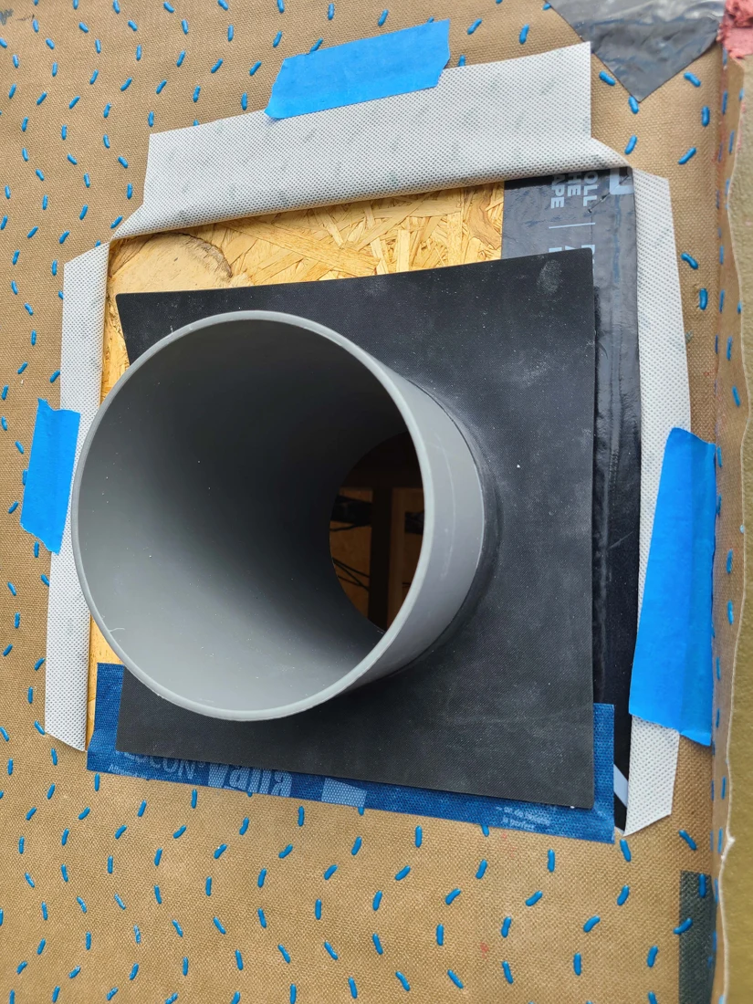
ACTUAL PHOTOGRAPH / REFERENCE
Look at the wall crossing
The source shows an EPDM gasket around a through-wall ventilation duct during installation. It is one stage of one assembly, not evidence that all weatherproofing and airtightness work is complete.
Ask: What is the complete, project-specific wall detail and who records continuity before the work is covered?
Photo source & use
Edward Louie Photography / Courtesy of the U.S. Department of Energy. Source record · BASC reuse guidance. Resized and encoded as WebP; no retouching. Checked 27 October 2026. Reference only; no DLG project, product endorsement or approval of another installation is implied.
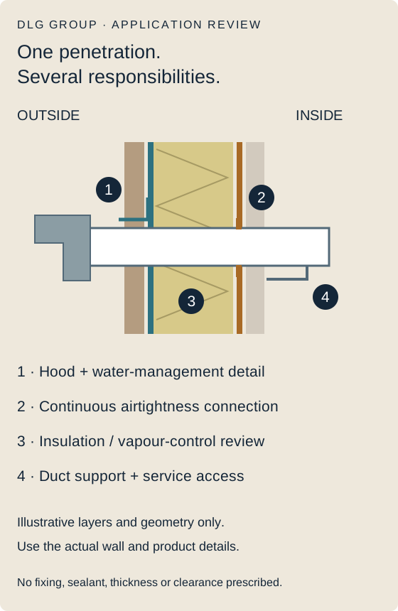
PNNL's balanced-system checklist addresses intake weather integration, air sealing, sealed duct connections, insulation and filter access. [V03] Turn those subjects into details for the actual wall and product, rather than copying a generic separation or material prescription.
| Interface | Ask to see | Who owns the answer? |
|---|---|---|
| Exterior hood and wall | Termination location, weather protection and the water-management connection to the actual wall assembly. | Ventilation installer plus envelope/renovation designer. |
| Airtightness boundary | The identified air-control layer and a continuous seal around the penetration; inspection before concealment. | The party responsible for the wall penetration and its reinstatement. |
| Cold-side ducts | Insulation and vapour-control continuity for the route and climate; resolved joints and supports. | Designer/installer for the selected assembly. |
| Unit, core and filters | A dimensioned service envelope, filter replacement path, safe access and readable model identification. | Installer and owner handover lead. |
| Water and cold operation | Condensate handling where the selected unit requires it, frost-control mode and service instructions. | Selected product designer/installer; record the manual revision. |
| Sound and vibration | Mounting/support proposal, duct/terminal sound review and a commissioning observation. | System installer, coordinated with room use and structure. |
5. Draw the distribution, not just the unit
A dedicated ventilation duct system and one coordinated with a central air handler are different scopes. PNNL describes both. [V02] Request a room/terminal schedule, the selected flow targets and operating modes, accessible adjustment and measurement points, return/transfer paths and any air-handler interlocks. A bedroom door being closed should be part of the design conversation.
ACTUAL PHOTOGRAPH / REFERENCE
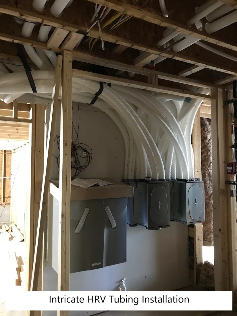
Ventilation ducts: read the route before the finish
A separately ducted HRV reference with numerous small ducts visible before enclosure. This is a photographed project, not a prescribed route, support arrangement or approval for a different building.
Ask: Can the distribution drawing, room schedule and before-concealment records be matched to each other?
Photo source & use
Mantell-Hecathorn Builders / Courtesy of the U.S. Department of Energy. Source record · BASC reuse guidance. Resized and encoded as WebP; no retouching. Checked 27 October 2026. Reference only; no DLG project, product endorsement or approval of another installation is implied.
Ask the designer to reconcile duct length, fittings, filter resistance, fan selection and expected installed airflow. Record which parts of an existing duct system have been assessed, which are retained, and any making-good work. PNNL's airflow-testing access guide explains why the ability to reach the test location must be planned, not discovered after the ceiling is closed. [V04]
Keep the agreed ventilation duty independent of a sales claim about the heat pump's size. Outdoor-air ventilation, local exhaust and pressure interaction need their own review for the actual dwelling and applicable local requirements. This guide does not prescribe a national minimum airflow or adopt one standard edition for every project.
6. A recovery rating is not a bill-saving percentage
HVI evaluates airflow and recovery performance and explains adjusted sensible and total recovery efficiency metrics, ASRE and ATRE. [V05] Record the exact metric, test conditions, airflow/static pressure and electrical input. Do not compare percentages with different definitions or substitute an attractive peak number for the relevant operating point.
An ideal temperature exercise
Assume outdoor air at 0°C, extract air at 20°C, and an explicitly assumed 75% temperature effectiveness. The ideal supply-side calculation is 0 + 0.75 × (20 − 0) = 15°C before any further conditioning.
For a separate summer case, outdoor air at 32°C and extract air at 24°C gives 32 + 0.75 × (24 − 32) = 26°C. These are original arithmetic exercises, not product predictions or comfort guarantees.
The assumed temperature effectiveness is not HVI SRE, ASRE or ATRE. This exercise excludes fan heat, leakage, imbalance, bypass, defrost, losses and moisture transfer. It does not calculate energy savings or say that the supply air has reached the room setpoint.
Fan electricity matters too: a hypothetical constant 80 W combined input is 0.08 kW × 24 hours = 1.92 kWh/day, or 700.8 kWh over 365 identical days. Actual modes, fan settings, filters and any preheater change the result. Unlike the separate fictional weather-day example in the Solar guide, this annual arithmetic explicitly assumes a constant input for the entire stated year; it is not a forecast for either house.
03 / Commissioning and careChapters 7–9 · Measured airflow, access, controls and comparable proposals.
7. Commission the installed airflow
PNNL's measurement guide covers methods for measuring mechanical ventilation airflow. [V07] Request a dated commissioning record with the operating mode, settings, measurement method/instrument, relevant filter condition, measured supply/exhaust and room results, together with the agreed acceptance basis. A catalogue airflow is not that installed measurement.
Turn measurements into a review question
For an invented target of 100 m³/h supply and 100 m³/h exhaust, suppose a record reports 92 m³/h supply and 108 m³/h exhaust. The difference is 16 m³/h. Ask the installer to explain the measurement conditions, distribution and adjustment against the project's acceptance criteria. The example supplies no universal allowable imbalance and makes no pressure prediction.
100 m³/h is approximately 58.9 cfm by unit conversion. Keep the units visible; the 100 m³/h target is an assumption for this exercise, not a recommended design rate.
Retain the initial and final settings, correction record and any unresolved work. Plan access so the agreed test can be repeated after relevant changes. [V04] Ask the provider to carry out tests through approved procedures; the owner should receive operating instructions rather than an improvised commissioning task.
8. Coordinate controls, solar and owner handover
Document normal ventilation, any timed/boost modes, cold-weather operation, central-fan interaction, filter reminders and owner override. A solar-surplus controller should not simply stop required ventilation whenever PV output falls. Agree the actual ventilation duty first, then account for its electricity within the wider energy model.
ACTUAL PHOTOGRAPH / REFERENCE
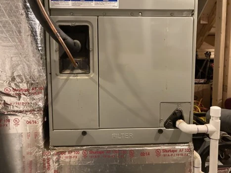
Air-handler filter and maintenance access
This PNNL reference is a vertical upflow air handler and its filter-access area—not the inside of the HRV pictured above. It illustrates why each piece of equipment needs its own service-access record.
Ask: Which filter belongs to which device, how is it reached, and where are its model-specific care instructions?
Photo source & use
PNNL / Courtesy of the U.S. Department of Energy. Source record · BASC reuse guidance. Resized and encoded as WebP; no retouching. Checked 27 October 2026. Reference only; no DLG project, product endorsement or approval of another installation is implied.
The Solar + Heat Pump reading distinguishes electrical input and useful heat. The Smart Homes guide distinguishes local operation, internet services and backup scope. Include ventilation fans and auxiliary equipment explicitly if outage operation is part of the brief; a small controls UPS is not a whole HVAC backup.
RenewAire's manufacturer guidance directs owners to both general residential care and the exact installation/operation manual for model-specific procedures. [V08] Keep that principle at handover: document filter type and source, intake inspection, service access, core-care method, drainage where applicable, fault contacts and maintenance responsibilities. Do not wash or chemically clean a core just because another product's instructions allow it.
9. Make the proposals answer the same questions
| Topic | Evidence to request from every firm |
|---|---|
| Design basis | Actual dwelling/occupancy, existing equipment, local requirements reviewed, flow targets and room schedule. |
| Selection | Exact HRV/ERV model, recovery metrics/conditions, airflow/pressure curve, power, sound and selected operating limits. |
| Routes and interfaces | Four-port identification, distribution/return paths, intake/exhaust locations, envelope details, insulation and service access. |
| Coordination | Heating/cooling interfaces, local exhaust, any pressure/makeup-air review, controls, cold operation and humidity strategy. |
| Scope and cost | Unit, ducts, electrical/controls, access work, wall/roof reinstatement, review/inspection duties, exclusions and service costs. |
| Test and acceptance | Installed measurement method, settings, supply/exhaust and room results, corrections and named acceptance responsibility. |
| Owner records | As-built routes, model/serial, manual revision, settings, maintenance schedule, warranties, support and unresolved items. |
| Future work | What changes when rooms, filters, air-handler settings or occupancy change, and which reviews/tests need repeating. |
Sources, scope and review dates
A comfortable temperature does not tell you whether outdoor air reaches the rooms. Treat fresh-air supply, stale-air removal, heat recovery, heating/cooling and moisture control as related functions with identifiable equipment, routes and operating evidence.
Sources and boundaries
Sources reviewed 21 October 2026. The questions, diagrams and arithmetic are original DLG editorial material. They do not select a product, approve a wall/duct assembly, establish a jurisdiction's required rate or predict a home's air quality, bills or humidity. Source-specific dimensions, filter minimums, code editions and manufacturer thresholds are not adopted as universal instructions.
- V01 · U.S. DOE Building Science Education, HVAC Whole-House Ventilation. System roles and outdoor-air exchange.
- V02 · PNNL / Building America Solution Center, Whole-House Ventilation Strategies for New Homes. Balanced systems, HRV/ERV transfer and distribution roles; no universal rate imported.
- V03 · PNNL / Building America Solution Center, Balanced HRV/ERV checklist. Building interfaces and installation/owner review subjects; its numerical prescriptions are not copied into this concept.
- V04 · PNNL / Building America Solution Center, Designing and Installing Mechanical Ventilation Systems to Enable Airflow Testing. Test access and physical planning.
- V05 · Home Ventilating Institute, HRV/ERV Buying Guide. Recovery metrics and certified performance comparison; current model listings must be verified for the actual quotation.
- V06 · PNNL / Building America Solution Center, Ventilation and Exhaust Strategies for Multifamily Housing. Examples separating room conditioning, ventilation, kitchen exhaust and supplemental dehumidification. Multifamily context; not a detached-house design.
- V07 · PNNL / Building America Solution Center, Measuring Mechanical Ventilation Airflow. Measurement methods and test records; local adoption/current standard edition remain project-specific.
- V08 · RenewAire, Maintenance and Cleaning. Manufacturer-specific manual/care reference, not an endorsement or a procedure for other brands.