
DLG GROUP · HVAC / BUILDING ENCLOSURE & EQUIPMENT SELECTION
Heat loss and heat-pump sizing: ask for the evidence.
Start with the rooms, building enclosure and design conditions. Follow the heat-loss example, then compare the proposed equipment’s output with the load at matching conditions.
ACTUAL PHOTOGRAPH / REFERENCE
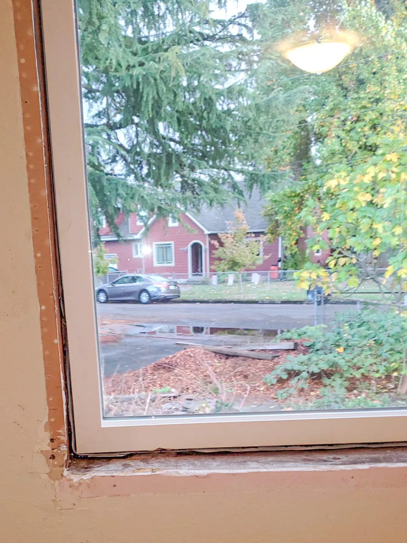
Read the opening before it is covered
The removed interior trim exposes the window perimeter and adjoining wall. The visible junction helps explain what needs recording before the finish is reinstated. The photograph is not a thermal survey, a leakage measurement or confirmation of a completed air or water seal.
Ask: Which air-control, insulation and water-management details will be inspected and photographed before this junction is closed?
Photo source & use
Edward Louie Photography · Courtesy of the U.S. Department of Energy. BASC image record · BASC reuse guidance. EXIF orientation, resized and WebP encoded; no crop or retouching. Source and reuse guidance checked 27 October 2026. Not a DLG installation, current product recommendation or approval of the pictured arrangement.
01 / Brief, enclosure & junctions
A floor-area figure and a large outdoor unit do not explain how a home will perform. Connect the enclosure you actually have, the improvements you intend to make, the room loads and the equipment data at the conditions that matter.
1. Define what the system must serve
ACCA identifies Manual J as its residential load-calculation method, Manual S as equipment selection and Manual D as residential duct design. These are different deliverables, not three names for a sales estimate. Ask which documents the proposal includes and who is responsible for them. [L01] [L02] [L03]
| Decision | Write it into the brief | Evidence to request |
|---|---|---|
| Whole home or selected rooms? | Conditioned boundaries, rooms, doors normally closed and any excluded spaces. | Marked plan and room/zone schedule matching the proposal. |
| Replacement or renovation? | Current wall, attic, window and leakage assumptions; identify planned changes separately. | Dated existing and proposed input sets, not an unexplained lower total. |
| Sole heating or supported heating? | Intended role of retained equipment, auxiliary heat and changeover controls. | Capacity/shortfall review and written operating sequence. |
| Other loads? | Keep domestic hot water, pool heating and EV charging distinct from room heating. | Separate thermal and electrical schedules; coordinate shared service capacity. |
Choose the brief before choosing the model. In a staged renovation, ask the designer to identify which improvements are assumed complete when the equipment is selected. A future insulation promise should not silently become the present home's design input.
2. Read the enclosure as an assembly
Four questions help organise the survey: where heat conducts, where air leaks, where water is managed and how the assembly can dry. An insulation label alone does not answer all four.
- Thermal layer: record the actual assembly, discontinuities and framing. Thermal bridges are paths through materials that conduct more readily than the surrounding insulation; cavity insulation does not describe every path. The Illinois training material explains this distinction. Its historical code examples are not current local requirements for your project. [L04]
- Air boundary: identify continuity at ceilings, openings and service penetrations. PNNL's vented-attic guide describes an air barrier aligned with the insulation, with the ceiling forming the boundary in that arrangement. An unvented roof is a different assembly. [L05]
- Windows: retain whole-product U-factor, SHGC, orientation and shading data. DOE distinguishes U-factor, which describes heat conduction, from SHGC, which describes admitted solar heat. These inputs answer different questions. [L06]
- Observed condition: photograph visible gaps, damp areas, damaged insulation and inaccessible sections. Mark unknown construction as unknown and ask how the uncertainty will be resolved.
U-factor and R-value must refer to the same assembly basis and consistent units before treating them as inverses. Do not invert a U-factor in W/(m²·K) and label the result as a U.S. customary R-value. Ask whether a quoted wall figure includes framing and junction effects.
3. Review the junction before it is covered
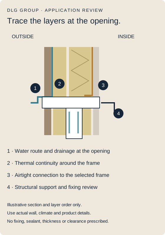
Ask for a detail that traces each control layer across the opening and shows how the selected frame is supported. Use the drawing to ask where the insulation stops, where the air seal connects and where any water can leave. A neatly filled cavity is only one part of that review.
For attic work, PNNL's checklist starts with moisture/damage assessment, ventilation and relevant combustion/electrical conditions, then addresses air sealing before insulation. It explicitly says fibrous insulation is not an air barrier. Ask the contractor to record preparation and concealed work before covering it. [L07] Treat those items as a scope conversation; this page does not select a sealant, clearance or insulation thickness.
02 / Load example & equipment selection
4. Follow one small heat-loss example
This invented steady-state winter exercise covers only one opaque wall area and one window. It is not a room or whole-home load calculation. No particular climate, wall build-up or product is represented.
Conduction only: Q = U × A × ΔT
Assume indoor 20°C (68°F) and outdoor −5°C (23°F): the temperature difference is 25 K. Use SI U-factors throughout. A temperature difference in kelvins has the same numerical size as a difference in Celsius degrees.
| Component | Net area | Before U | Before heat loss | After U | After heat loss |
|---|---|---|---|---|---|
| Opaque wall, excluding opening | 12 m² | 0.35 W/(m²·K) | 0.35 × 12 × 25 = 105 W | 0.20 W/(m²·K) | 0.20 × 12 × 25 = 60 W |
| Window, separate from opaque wall | 4 m² | 1.80 W/(m²·K) | 1.80 × 4 × 25 = 180 W | 1.20 W/(m²·K) | 1.20 × 4 × 25 = 120 W |
| These two components only | 16 m² total | — | 285 W = 0.285 kW thermal | — | 180 W = 0.180 kW thermal |
The difference is 105 W, or about 36.8% of these two components' calculated conduction loss at the same temperature difference. If those exact conditions lasted one hour, the heat quantities would be 0.285 and 0.180 kWh thermal. This is not electrical use or annual energy saving.
The assumed U-factors represent the complete component basis used in this exercise. Separate junction/edge losses, other surfaces, ground effects, infiltration, ventilation, ducts, solar/internal gains and dynamic effects are omitted. Do not double count the window as both window area and opaque wall. Do not use the 36.8% result as a whole-home saving, reduce an equipment size by that percentage or apply it to an electricity bill.
5. Compare the home's load with capacity at the same conditions
PNNL's cold-climate selection guide calls for both heating and cooling load calculations, accurate enclosure inputs and capacity data at design conditions. It cautions against extra rounding-up of a completed Manual J result and against selecting from nameplate capacity alone. The manufacturer's maximum and minimum output across outdoor temperatures are relevant to the match. [L08]
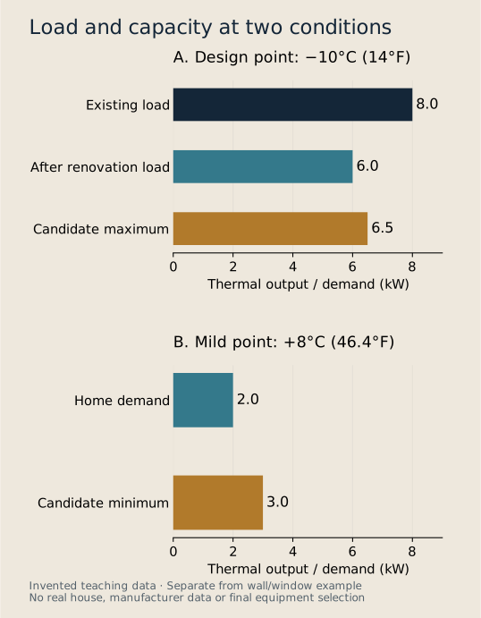
Read the two operating points
At the invented −10°C (14°F) design point, an 8.0 kW load and 6.5 kW available maximum leave 1.5 kW thermal unmet before any separately designed support. An independently calculated post-renovation load of 6.0 kW would put that same assumed maximum 0.5 kW above the load at this one point. The figure does not establish a final equipment selection.
At a separate +8°C (46.4°F) mild point, the invented 2.0 kW demand is 1.0 kW below the assumed 3.0 kW minimum continuous output. The designer should address cycling and control behaviour. These two points do not locate a balance point or predict annual operating hours.
Request the exact indoor/outdoor combination and the performance table page used for each comparison. Ask how defrost, auxiliary heat and distribution conditions are treated. A cold-weather output figure, a seasonal efficiency label and an electrical input figure describe different things. None can replace the missing rows of the design record.
6. Check cooling, humidity and room delivery
PNNL's ductless guide describes room/zone and whole-home calculations, matched indoor/outdoor equipment and expanded manufacturer data at the design conditions. It also treats indoor-unit location, electrical assessment and commissioning as part of the work. A room left behind a closed door needs its delivery strategy explained. [L09]
For a ducted proposal, request the duct-design scope, available external static pressure, intended airflow and a measurement plan. For a ductless proposal, request the zone boundaries, head locations and capacity allocation for the actual combination. Ask the designer to show cooling sensible and latent performance and the humidity-control strategy rather than assuming heating capacity answers those questions.
Keep outdoor-air ventilation explicit: an enclosure improvement changes the assumptions to review, while a heating/cooling unit does not by itself establish the ventilation route. Continue with the installed-airflow evidence guide. The solar integration example concerns thermal/electrical timing; solar production does not determine the building's design heating load.
03 / Sequence & comparable proposals
7. Sequence assessment, improvements and equipment
- Survey and document: plans, assemblies, window labels, condition, existing equipment and comfort complaints.
- Resolve the enclosure scope: assess moisture and relevant safety conditions; agree the work and its evidence before covering junctions.
- Calculate the agreed scenario: existing and proposed inputs must be distinguishable. DOE's sizing training explicitly includes efficiency improvements as a way to reduce heating/cooling loads. [L10]
- Select and coordinate: compare equipment performance with design loads, then resolve distribution, ventilation, auxiliary heat, electrical work and controls.
- Install, measure and hand over: retain the final model combination, settings, commissioning readings, owner instructions and the responsible contacts.
A failed system may require replacement before every planned improvement is complete. In that situation, ask for the interim scenario and the expected later operating conditions in writing. The aim is a traceable decision, not an assumed universal order for every project. Review the renovation permits and sequence guide for local approval preparation.
8. Request a design record you can compare
| Record | What should be visible? | Question for the firm |
|---|---|---|
| Survey and assumptions | Measured areas, construction, glazing, leakage basis, shading and conditioned boundaries. | Which inputs were inspected, tested, estimated or left unresolved? |
| Design conditions | Location, indoor/outdoor design values and the chosen weather reference. | Do the equipment rows use the same design conditions? |
| Load calculation | Room/zone and whole-home heating and cooling results, with the calculation method. | Can I see the input report and the version after agreed enclosure work? |
| Equipment selection | Exact matched model numbers, extended data, selection method and support-heating scope. | Where do maximum and minimum outputs sit against the loads? |
| Distribution and moisture | Duct/zone plan, airflow, controls and humidity strategy. | How will closed rooms, cooling moisture removal and ventilation be checked? |
| Electrical and solar coordination | Separate equipment/service assessment, auxiliary loads and backup limitations. | Who coordinates the electrical scope and the actual outage operating plan? |
| Commissioning and handover | Agreed readings, settings, manuals, maintenance access and responsible parties. | Which measured results will be delivered, and what triggers corrective work? |
| Commercial exclusions | Permits, repairs, removal, access work, testing and document delivery included or excluded. | Are competing prices covering the same scope? |
Use the three-proposal worksheet for solar integration notes. Its solar profile does not certify this HVAC design; attach the heating/cooling reports as separate evidence.
Sources, assumptions and review dates
Sources and limits
Primary sources checked 21 October 2026. The public summaries below identify methods and review concepts; they do not reproduce the purchased manuals, determine local code adoption or complete a design for a specific property. All numbers and drawings on this page are original illustrative teaching material.
- ACCA: Manual J — Residential Load Calculation. Method and residential scope.
- ACCA: Manual S — Residential Equipment Selection. Selection scope.
- ACCA: Technical manuals. Manual D duct-design role.
- University of Illinois Smart Energy Design Assistance Center: Air barriers and thermal bridging (2021 training PDF). General mechanisms only; its code examples are historical.
- PNNL: Air sealing and insulating ceilings in vented attics. Specific vented-attic assembly concept.
- DOE Building Science Education: ENERGY STAR for windows. U-factor and SHGC roles, not a product recommendation.
- PNNL: Attic air sealing and insulation checklist. Preparation and work documentation.
- PNNL: Cold-climate heat-pump sizing and selection. Loads, design-condition capacity and modulation; not a universal sizing ratio.
- PNNL: Ductless mini-split heat pumps. Zones, matched equipment and commissioning.
- DOE Building Science Education: Cold-climate heat-pump sizing training. Efficiency improvements and sizing sequence.