
DLG Insights / Energy Recovery
Recover heat from shower drain water.
A drain-water heat exchanger can put some of the warmth headed for the sewer back to work. Follow the two water lines to see what actually happens.
Two water lines. One exchange of heat.
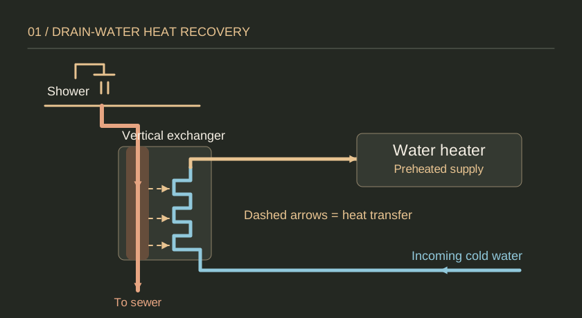
- Warm drain water flows down. It leaves the shower, passes through the vertical drain section, and continues to the sewer.
- Cold supply water moves through a separate tube. In the vertical design shown, that tube wraps around the drain pipe.
- The heater receives warmer supply water. The two streams stay separate. The exchanger recovers heat while both streams flow.
What happens inside the exchanger?
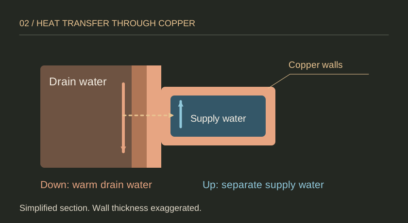
As warm drain water runs down the inside surface of the vertical pipe, it can spread into a thin film. Heat travels through the copper walls into the cooler water in the surrounding tube. The solid arrows show water flow; the dashed arrow shows heat moving across the metal.
A unit without heat storage works when the warm drain flow and cold supply flow overlap. A shower commonly provides that overlap. A tub that drains after filling usually does not.
Worked example / U.S. units
How preheating changes the heater’s job
Suppose the incoming water is 50°F and the heater’s target in this example is 120°F. If the exchanger raises the incoming water to 68°F, the heater starts from a warmer inlet.
- Without preheating
- 50°F → 120°F
70°F rise supplied by heater - With preheating
- 68°F → 120°F
52°F rise supplied by heater
For the same amount of water, the example shows an 18°F reduction in the temperature rise supplied by the heater. These assumed temperatures explain the mechanism; they are not installation settings, a product rating, or a utility-bill estimate.
What to check in your home
- Drain route: Does the shower drain reach an accessible vertical section with room for the proposed unit?
- Connection plan: Where will the preheated line go, and what access will remain for service?
- Use pattern: How often does the household shower, and when do warm drain flow and cold supply flow overlap?
- Before buying: Ask a qualified installer to confirm fit, performance at the expected flow, and applicable local requirements.
Next: See how graywater reuse differs or compare water-heating systems.
Sources and scope
DLG diagrams are educational concepts. This guide illustrates a vertical, non-storage unit; other layouts and products can differ.